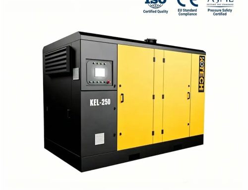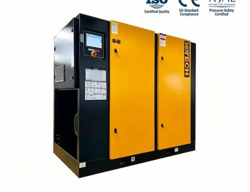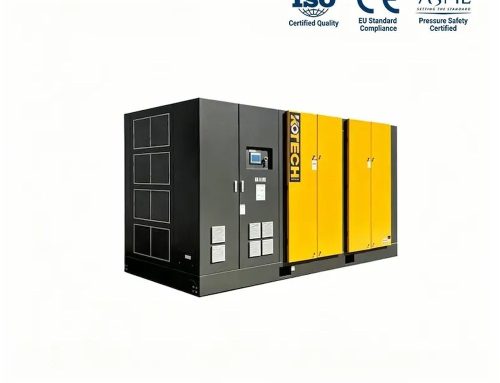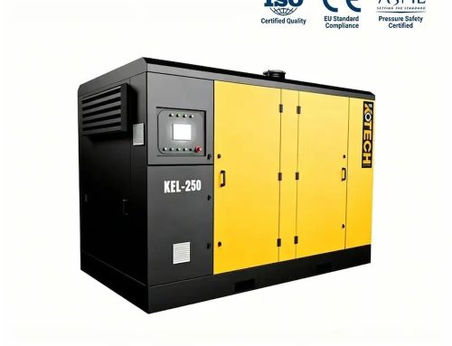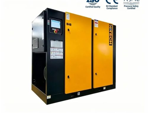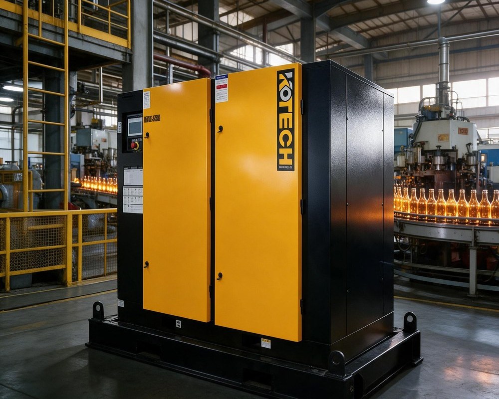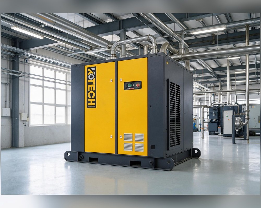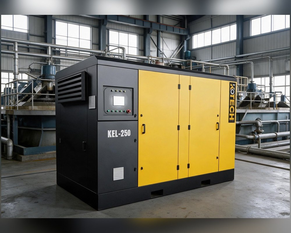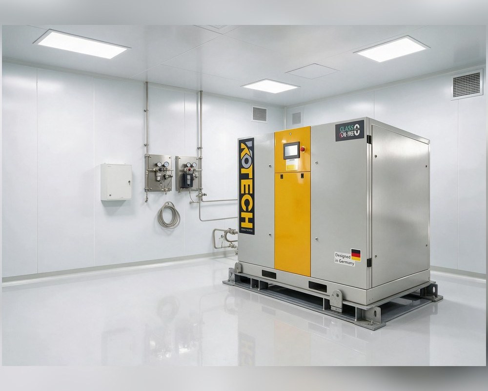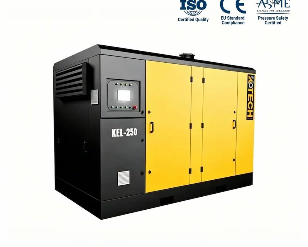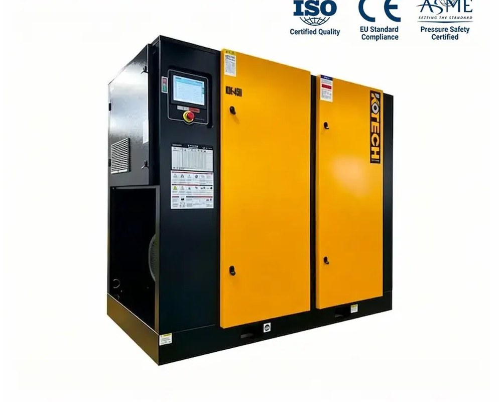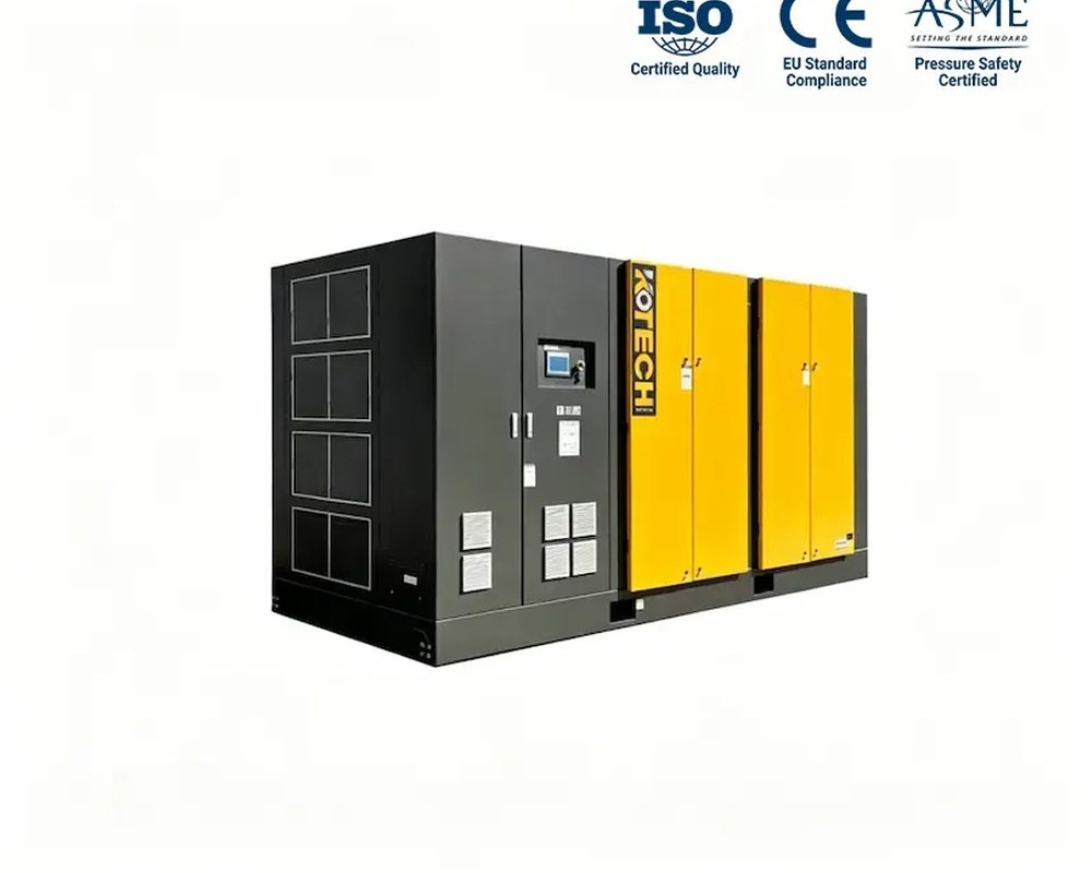




A modern paper machine is one of the most continuous, air-hungry processes in manufacturing: the sheet travels at more than 1,500 metres a minute through the forming, pressing and drying sections, held, guided, trimmed and controlled at dozens of points by compressed air. What surprises mills upgrading their utility systems is that most of this air is wanted in large volume but at modest pressure, commonly 2 to 5 bar rather than the 7 to 8 bar of a general factory network. Supplying that duty from a standard compressor throttled or regulated down wastes energy on every revolution, which is why purpose-built low-pressure screw machines have become standard in paper-mill air audits. This guide maps the real air demands of a paper machine and shows where the KOTECH KEL low-pressure range fits.

Where a paper machine actually uses compressed air
Air appears throughout the machine. In the forming and press sections, air showers and blow-off nozzles clean fabrics and rolls; pneumatic actuators position doctors and tail threading equipment; felt and wire conditioning uses controlled blow. In the dryer section, air-operated controls manage steam and condensate systems, and around the reel and winder, air shafts, chucks and braking equipment run on pneumatic power. Edge trim nozzles and sheet stabilisation systems on high-speed gap-formers can consume particularly large continuous volumes. Instrument and control air is comparatively small but must be clean, dry and uninterrupted.
The key engineering fact is the pressure split. A significant share of the process air — conditioning showers, blow-offs, stabilisation, trimming — is needed at only about 2 to 5 bar(g), while a smaller stream of instruments and critical controls wants the conventional 7 to 8 bar network at high quality. Treating the whole mill as one 8 bar load means compressing every cubic metre to high pressure, then throwing the surplus away through regulators before it reaches a 3 bar nozzle. Splitting the duty into a low-pressure process system and a smaller high-pressure instrument system is the single biggest structural saving a mill can make.
- Fabric/roll conditioning, blow-offs and sheet stabilisation: high volume, roughly 2 to 5 bar.
- Edge-trim nozzles on high-speed machines: large continuous flow.
- Pneumatic actuators, doctors and reel/winder equipment: intermittent process air.
- Instrument and control air: smaller flow at 7 to 8 bar, requiring clean dry air at high reliability.
Why a low-pressure compressor saves energy on this duty
Compression work follows pressure ratio: raising air to 8 bar when the process needs 3 bar performs thermodynamic work that is immediately discarded across a pressure-reducing valve, and the loss repeats continuously because paper machines run around the clock for weeks between shutdowns. A screw airend optimised for low built-in ratio, with a larger displacement and wider rotors, moves the same volume to 2 to 5 bar at materially lower specific energy. On a duty measured in thousands of operating hours and tens of cubic metres per minute, the electricity difference typically repays the dedicated machine quickly and keeps saving for the life of the machine.
Low-pressure frames also behave better under variable demand. Paper grades and machine speeds change, trim and conditioning systems cycle, and a variable-speed low-pressure machine follows that profile instead of loading and unloading against a receiver. Stable low header pressure also improves nozzle performance: blow-off and stabilisation systems are sensitive to pressure fluctuation, so a dedicated, controlled supply improves both energy use and sheet runnability. The remaining high-pressure network can then be sized for the real instrument load, often with a smaller, higher-quality machine and proper drying.
Real KOTECH KEL low-pressure screw compressor specifications
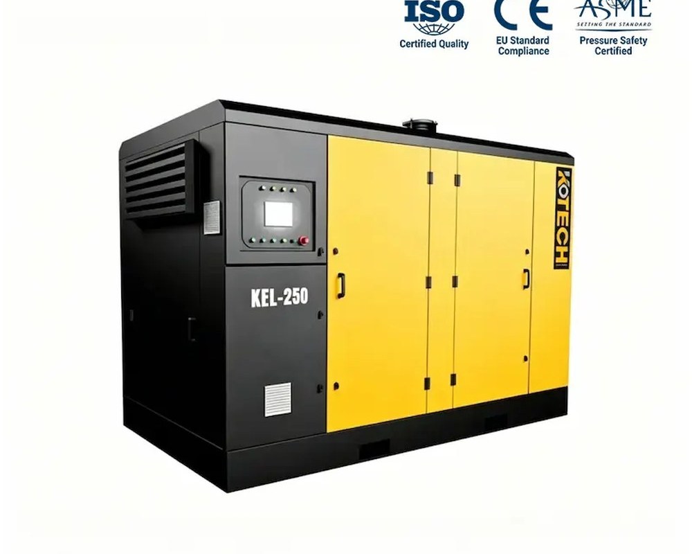
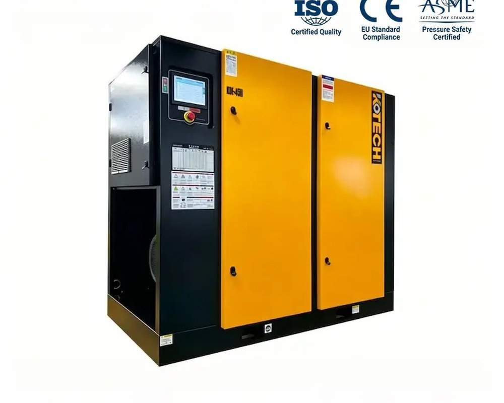
Current factory figures at the stated pressure points from the KOTECH product page; the KEL line covers 1.5 to 5 bar in fixed-speed and VSD versions.
Read each row at the true header pressure: the same frame delivers less volume as pressure rises. A variable-speed KEL frame typically trims between about 25 and 100 percent of the published flow, so choose the frame at maximum demand and let speed control handle the average.
Sizing the two-pressure air system
The reliable method is an air-demand study rather than a nameplate guess. Log the low-pressure header and the 8 bar network separately for at least a week of representative production, isolating the large continuous consumers — conditioning, stabilisation, trim — from intermittent actuators and instruments. Where temporary metering is impractical, calculate nozzle and shower flows from supplier data at real nozzle pressure and apply realistic simultaneous-use factors. The low-pressure compressor is then sized at maximum simultaneous flow with one unit of redundancy, while the high-pressure machine is sized only for the instrument and control load at the required dew point and reliability class.
Air quality should be specified per stream rather than over-treating everything. Process conditioning air must be free of free water and oil aerosol to protect fabrics, rolls and product; instrument air should meet the plant’s control-valve specification with refrigerated or desiccant drying as required. Because paper-mill utility rooms are warm and humid, intake placement in cool clean air, effective after-cooling and condensate drainage protect both dryer load and nozzle performance. Piping headers should be sized for low velocity so the far end of a long machine still sees the design pressure.
- Meter the 2 to 5 bar process load separately from the 7 to 8 bar instrument load before sizing.
- Size low-pressure capacity at maximum simultaneous flow plus one redundant unit for a machine that rarely stops.
- Use variable-speed trim on the low-pressure header to follow grade and speed changes.
- Treat air quality per stream and keep intake air cool, with correct after-cooling and drainage.
Reliability in a continuous mill
Paper machines punish utility downtime: a sheet break caused by an air trip cascades into lost production, broke reprocessing and a lengthy re-threading sequence. The low-pressure station should therefore be designed N+1 with automatic changeover, run-hour equalisation and alarms that surface a developing fault before it reaches the machine. Routine service on the KEL frames — intake filters, fluid, separators and cooling — can then be scheduled around planned machine stops rather than the calendar. Building the compressor room with space for a future frame, and piping the low and high-pressure headers independently from the start, lets the system grow with machine speed-ups without re-plumbing the mill.
Buying tips
- Split paper-machine air into a 2 to 5 bar process system and a smaller 7 to 8 bar instrument system instead of regulating everything down.
- Choose a purpose-built low-pressure screw airend; energy wasted across reducing valves runs 24/7 on a paper machine.
- Size from metered header demand at the real nozzle pressure, including trim and stabilisation at maximum machine speed.
- Specify N+1 low-pressure capacity with automatic changeover to protect against sheet-break downtime.
- Match drying and filtration to each stream and place the intake in cool, clean air to control humidity and dryer load.
Frequently asked questions
What air pressure does a paper machine need?
Why not just run an 8 bar compressor and regulate the air down to 3 bar?
Which KOTECH KEL frame suits a paper machine process header?
Does paper-machine process air need drying?
How do I find the real low-pressure demand of my machine?
What happens if the process air supply fails?
Share your paper machine width and speed, the low-pressure consumer list and a week of header flow data if available, and our engineers will size a split KOTECH KEL low-pressure plus instrument-air station with redundancy and variable-speed trim.