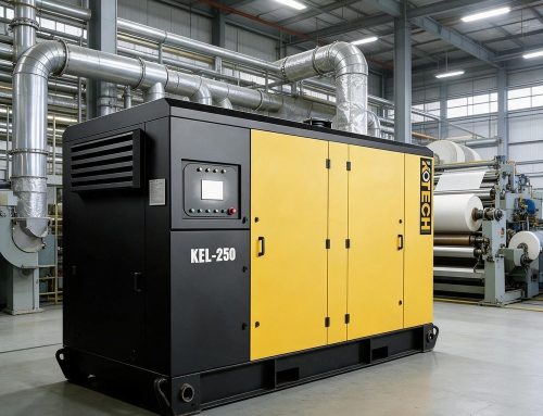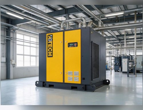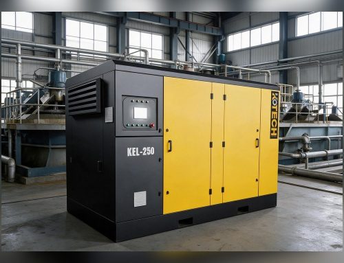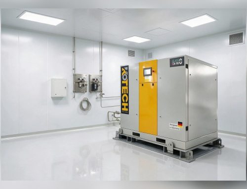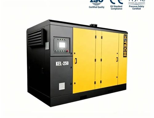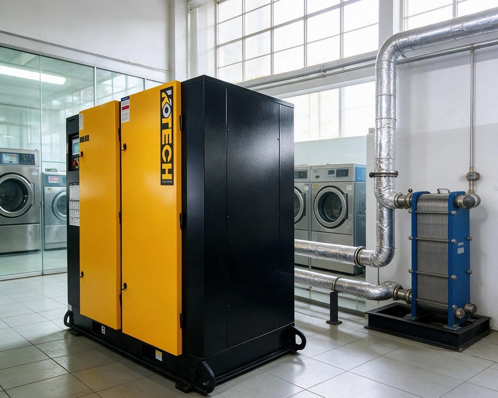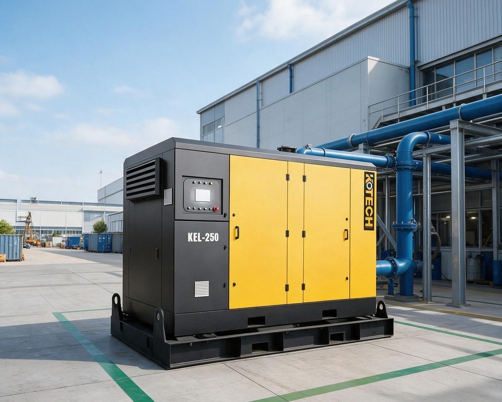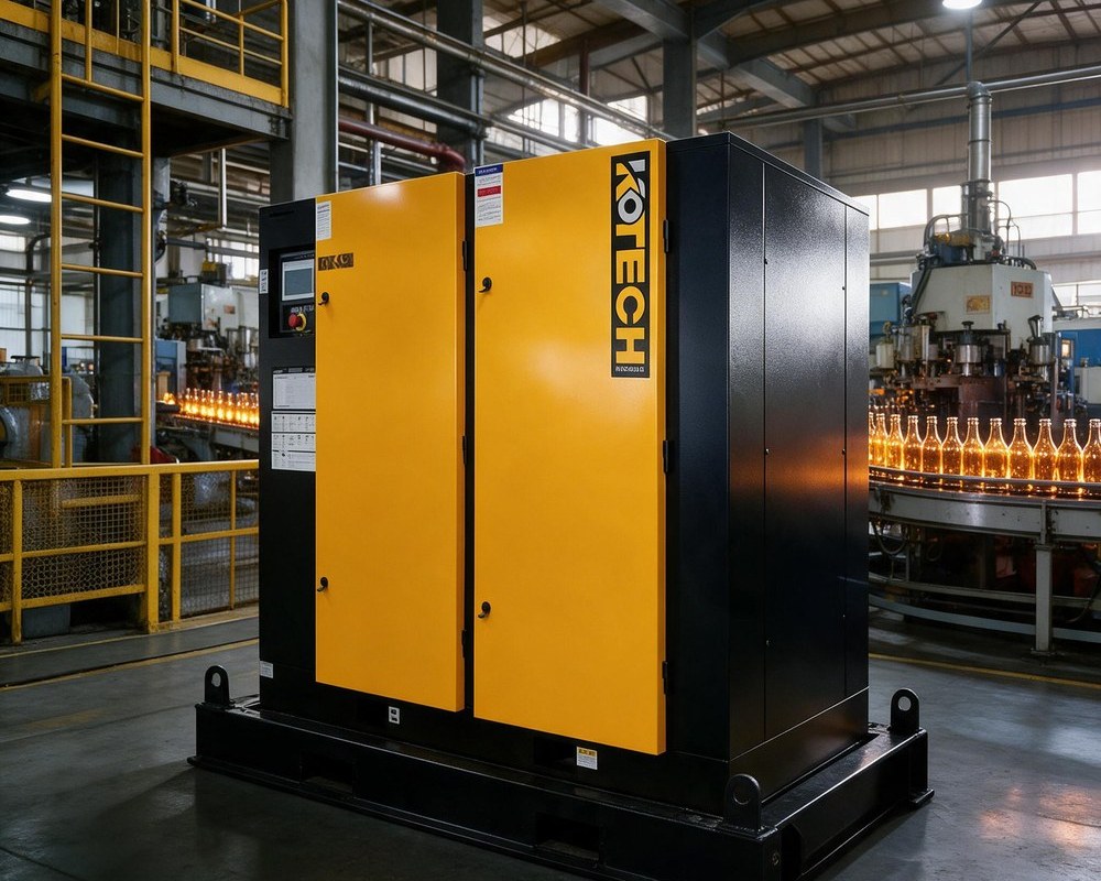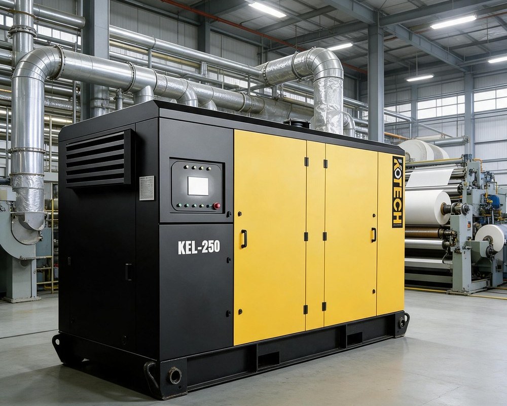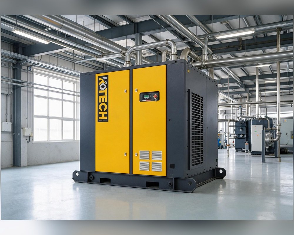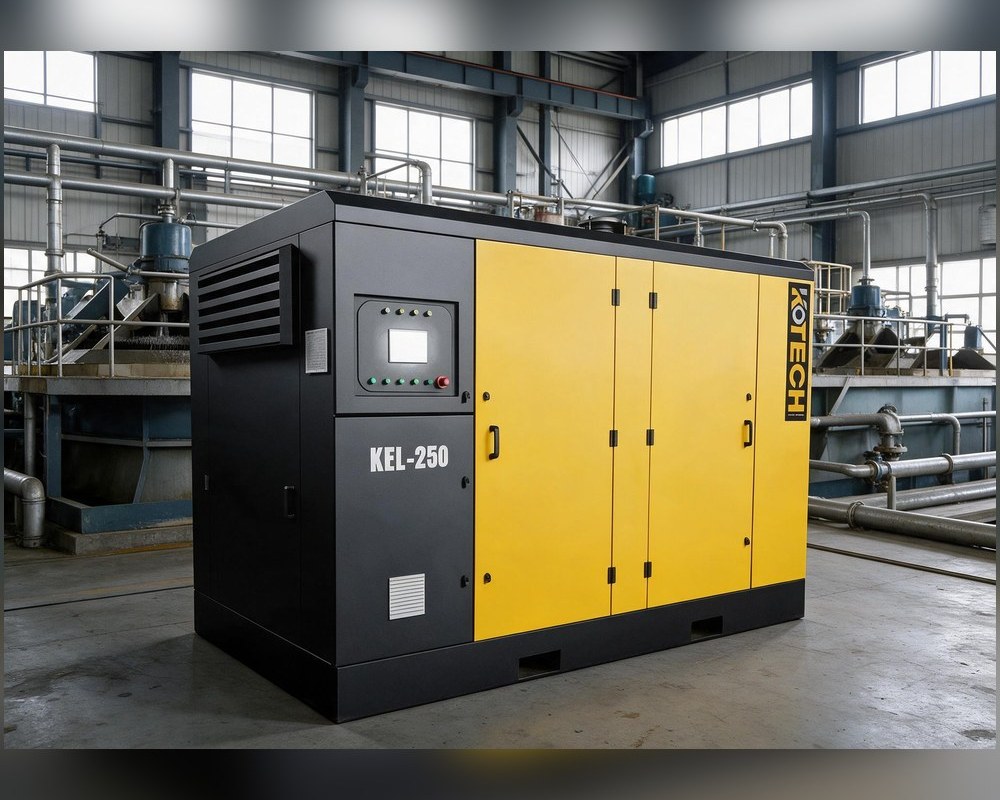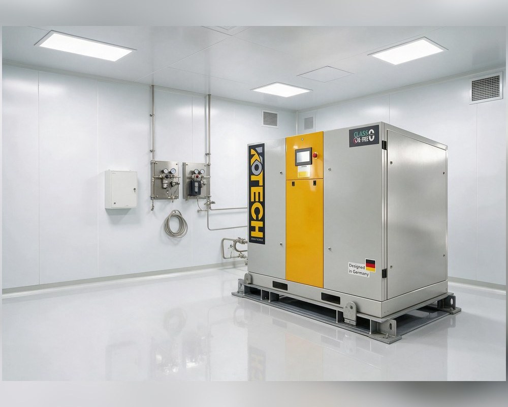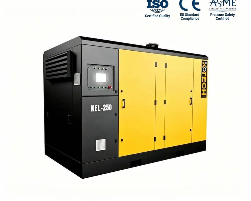




Autoclaved aerated concrete (AAC) plants look like simple block factories from the outside, but their air system hides a split personality. Fly ash and sand must be conveyed pneumatically, silos need fluidising air and slurry tanks benefit from aeration and agitation – all at low pressure – while mould clamps, crane hoists and packaging lines demand standard 7-8 bar air at the same site. Producing the whole mix on 8 bar compressors and regulating the low-pressure loads down wastes electricity every shift. The efficient layout is a split station: a dedicated low-pressure screw compressor, commonly rated at 2-4 bar, handles the bulk and process air, while a conventional machine serves the actuators. This guide sizes the low-pressure side for a real AAC plant, with KOTECH KEL data.

Where air goes in an AAC plant – and at what pressure
An AAC line mixes sand or fly ash with cement, lime and water, adds a small amount of aluminium paste, pours the slurry into moulds, lets the chemical reaction rise the cake, cuts it with wires and cures the blocks in autoclaves under steam pressure. It is worth being precise about the air loads: the rising of the cake itself is a chemical gas reaction, not compressed-air aeration, so no compressor ‘blows up’ the blocks. The compressed-air loads are the handling and process jobs around it.
The low-pressure group is substantial. Fly ash and sand are commonly delivered by dilute-phase pneumatic conveying at roughly 1.5-3 bar; silo and hopper fluidisation pads use a soft continuous flow to keep powder bridging-free; slurry and mortar mixing tanks use agitation and aeration air; air knives and cooling duties appear along the line; and filter cleaning and bagging use pulses of low-pressure air. The high-pressure group is equally real: mould clamp cylinders, autoclave-door hardware, pneumatic hoists and valves on the crane, tilting and cutting equipment, and the packaging and cubing line all want 6-8 bar.
- Low pressure (about 1.5-4 bar): dilute-phase conveying, silo fluidisation, tank aeration, air knives, filter cleaning.
- Standard pressure (6-8 bar): mould clamps, hoists and valves, door hardware, packaging and cubing.
- The cake rise is a chemical reaction – do not size air plant against it.
The cost of one pressure for every load
When the entire plant is fed from an 8 bar header, the conveying and fluidisation loads receive air that has been compressed to more than twice their working pressure and then throttled through regulators. Each unnecessary bar carries an energy penalty of roughly 6-8 percent on a widely used rule of thumb, and a conveying line running thousands of hours a year multiplies that penalty into a serious annual number. The pressure drop through dryers and filters is also wasted twice: once to create the high pressure, once to throw it away.
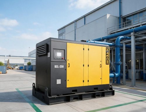
A split station removes the structural waste. A low-pressure compressor such as the KEL works close to the 2-4 bar design point of the air end and feeds a dedicated low-pressure header sized for the larger volumetric flow; the existing 7-8 bar compressors shrink back to the actuator load they were actually meant for. On multi-shift AAC production this re-arrangement is usually the single largest air-energy improvement available without touching the process itself.
KOTECH KEL low-pressure screw compressors at 3 bar: published VSD ratings
Variable-speed frames suited to AAC conveying, fluidisation and aeration duties. Air delivery is the published turndown range at 3 bar.
The table gives VSD turndown at the 3 bar rating used for most fly ash and sand conveying. Check the 4 bar figures (lower flow on the same frame) when long lines or sand duty set the design pressure, and avoid sizing on nameplate maximum without margin.
Designing the two-header layout
Keep the pressure families physically separate. A low-pressure header in larger diameter serves the conveyors and fluidisation, because low-pressure air moves at high volume and narrow mains bleed pressure quickly; a conventional header serves the clamps and packaging. The low-pressure compressor should sit close to the conveying take-off where possible, with its own receiver to absorb the pulsed demand of the conveyor, and the fluidisation circuit should include proper filtration and oil-free-compatible air quality where product contact is a concern – depending on plant standards, an oil-free or tightly filtered solution may be specified for the air that can reach the powder.
Controls and redundancy deserve attention from day one. Sequence the low-pressure VSD as trimmer against any fixed-speed base unit, interlock the conveying and fluidisation branches so a leak in one cannot drag down the whole station, and include alarms for low header pressure because a starved conveyor blocks rather than slows. Plan the pipe routes and receiver capacity during the plant layout phase – retrofitting a second header around a running AAC line is far more expensive than installing it in the original utility design.
- Dedicated larger-bore low-pressure header, close to the conveyor take-off, with its own receiver.
- Separate 7-8 bar header for clamps, hoists and packaging; do not cross-connect regulators as a habit.
- Use VSD to follow batch conveying; interlock branches to isolate leaks.
- Specify the required air quality for powder-contact duties explicitly.
Reliability in a dusty building-materials environment
AAC plants are hard on rotating equipment: sand and cement dust find every seal, wash-downs are frequent and autoclave areas are hot and humid. A low-pressure station needs good intake filtration with accessible elements, a canopy or machine room separated from the dustiest transfer points, and service intervals planned around actual running hours in 24-hour production. Fluidising and conveying air should be dried and filtered to the level the conveyor and product require; damp air in a fly ash line creates exactly the blockage that stops a siler truck or a batching cycle. Specifying consumables, filters and separator elements at procurement rather than after the first stoppage keeps the block line running through the autoclave cycles that generate the plant’s revenue.
What an AAC plant should specify
- List the low-pressure loads separately from the 7-8 bar actuator loads before sizing anything.
- Size conveying air from tonne-per-hour rate, line length and diameter, not from a single CFM guess.
- Choose the 3 bar frame for fly ash and short lines; check 4 bar flow for sand and long lines.
- Install a dedicated larger-bore low-pressure header and receiver from the start, not as a retrofit.
- Require VSD for batch conveying and define the air quality needed for powder-contact air.
- Protect the machines from cement and sand dust with good intake filtration and location.
Frequently asked questions
Do AAC blocks rise because of compressed air?
What pressure do pneumatic conveying lines in an AAC plant need?
Can one 8 bar compressor run the whole AAC plant?
How is a low-pressure compressor sized for conveying?
Does the conveying air need drying and filtering?
Designing or upgrading an AAC block plant air station? Split the low-pressure conveying air from the 8 bar actuator load and size the KEL VSD frames against your real tonne-per-hour data. Send your conveying layout for a sized proposal.