
How do Rotary Screw Air Compressors Work Diagram?
Firstly, let’s see the HD animation of the working principle of German GEA screw compressor, it’s so cool! Let’s start with a few moving pictures to get a feel for it:


Rotary Screw Air Compressor History
■ In 1934 Lysholm (Riesmann), a professor at the Royal Swedish Academy of Engineering, invented the first twin-screw gas compressor.
■ From the 1960s, oil-injected twin-screw units are used in refrigeration units. Sweden SRM (twin screw) first invented bilateral asymmetric profile screw, so that the efficiency of the screw machine greatly improved.
■ 1960 French Zimmern (Xin Maien) (single screw) invented a new structure of the single screw. 1962 trial production of the first prototype.
■ In the early 70s, the Netherlands GRASSO (GRASSO) made the first single-screw refrigeration compressor.
■ 1972, Japan began production of single-screw air compressors.
■ 1982, began production of single screw refrigeration compressor.
Screw compressor cylinder is equipped with a pair of intermeshing spiral yin and yang rotor, the two rotors have a few concave teeth, the two rotate against each other. Between the rotor and the casing and rotor clearance is only 5 to 10 silk, the main rotor (also known as the yang rotor or convex rotor), by the engine or motor drive (most of the motor drive), the other rotor (also known as the yin rotor or concave rotor) by the main rotor through the formation of the oil film formed by the injection of oil to drive, or by the main rotor end and the concave rotor end of the synchro-gear drive.
So there is no metal contact in the drive (theoretically). The length and diameter of the rotor determine the compressor discharge volume (flow rate) and discharge pressure; the longer the rotor, the higher the pressure; the larger the rotor diameter, the higher the flow rate.
The spiral rotor groove is filled with gas as it passes through the suction port. When the rotor rotates, the rotor groove is closed by the wall of the casing, forming a compression chamber, when the rotor groove is closed, the lubricating oil is sprayed into the compression chamber to seal.
Cooling and lubrication. When the rotor rotates and compresses the lubricant + gas (referred to as oil-gas mixture), the volume of the compression chamber decreases and the oil-gas mixture is compressed towards the exhaust port. When the compression chamber through the exhaust port, the oil and gas mixture from the compressor discharge, complete a suction – compression – exhaust process.
Each rotor of a screw machine is supported by a friction-reducing bearing, which is held in place by an end cap near the end of the rotor shaft. The inlet end is supported by roller bearings, and the exhaust end is supported by a pair of conical roller bearings usually on the exhaust end of the bearings so that the rotor positioning, that is, thrust bearings, resistance to axial thrust, to withstand radial loads, and to provide the necessary axial operation of the minimum clearance.
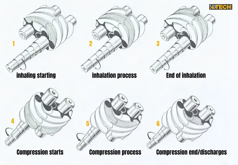
The operating cycle can be divided into three processes: suction, compression and exhaust. As the rotor rotates, each pair of intermeshing teeth successively complete the same work cycle.
Rotary Screw Compressor Advantages
1) High reliability. Screw compressor parts less, no wearing parts, so it runs reliably, long life, overhaul intervals of up to 4-8 millionh.
2) Easy to operate and maintain.
3) Good power balance. Especially suitable for use as a mobile compressor, small size, light weight, covers an area of less.
4) Strong adaptability. Screw compressor has the characteristics of forced gas transmission, volumetric flow is almost independent of the exhaust pressure, in a wide range to maintain high efficiency, in the compressor structure does not make any changes in the case of a wide range of work materials.
5) Multi-phase mixed transport. Screw compressor rotor teeth actually leave a gap between the surface, and thus can withstand the impact of liquid, can be transported containing liquid gases, dust-containing gases, easy to polymerisation of gases and so on.
Rotary Screw Compressor Disadvantages
(1) high cost. Because the rotor tooth surface of the screw compressor is a space surface, need to use special tools in the expensive special equipment for processing. In addition, the screw compressor cylinder machining accuracy also has high requirements.
(2) can not be used for high-pressure occasions. Due to the rotor stiffness and bearing life and other aspects of the limitations, screw compressor can only be used for medium and low pressure range, exhaust pressure is generally not more than 3MPa.
(3) can not be used for miniature occasions. Screw compressors rely on gap sealing gas, generally only volume flow greater than 0.2m/min, screw compressors have superior performance.
Adjustment of displacement:
Variable speed adjustment, screw compressor displacement and the number of revolutions is proportional to the relationship. Therefore, change the number of compressor speed can achieve the purpose of regulating the exhaust volume.
Stopping regulation:
The use of compressor stopping to adjust the amount of exhaust, there are two common forms:
For air compressors greater than 5kW this is the most commonly used method, with a wide range of regulation and low losses, in effect it is a combination of on/off regulation with various unloading systems.
The length of the idling cycle can be based on the number of starts and stops the motor can withstand without overheating, and the economy during operation. The latter because the system can decide to stop, or continue idling, depending on the direction of air consumption.
Controlled intake regulation:
The use of the compressor suction pipe on the inlet valve to regulate. Controlled intake regulation is divided into two kinds of stopping intake and throttling intake.
Inlet and outlet pipe connection regulation:
From the structure of the device, this method of regulation is simple, it only needs to be installed in the discharge pipeline a regulating valve. When regulating the working condition, the compressed gas flows back to the suction port along the bypass pipe through this regulating valve.
Idle regulation:
It is actually stopping the suction and inlet and exhaust pipe connectivity regulation jointly used a comprehensive regulation method, using a cut-off in the suction at the same time, can make the inlet and exhaust pipe connectivity of the load reduction valve. Idle regulation of the diagram shown in Figure 4-49. It can be stopped on the basis of suction regulation diagram, taking into account the gas to the intake pipeline (atmosphere) discharge (installed in the compressor discharge check valve before the connecting pipe) and get.
Slide valve adjustment:
Slide valve is a traditional compressor regulation, by adjusting the position of the slide valve to change the compressor’s discharge volume.
Usually used in small air compressors, such as automotive air conditioning compressors, household air conditioning compressors, refrigerator compressors and so on. For large compressors, often use electronic control, frequency conversion speed control and other higher precision regulation to meet the requirements.
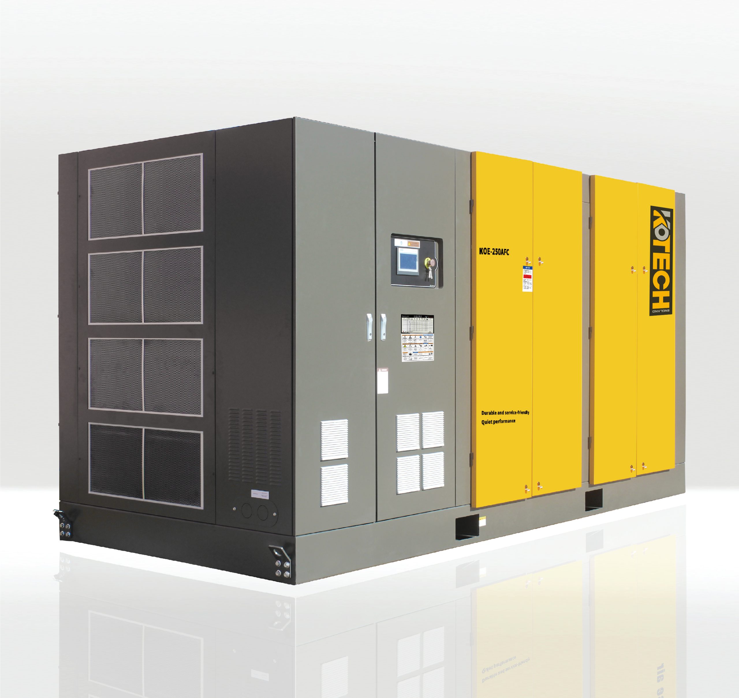
KOE Series Rotary Screw Air Compressor
With the latest generation of KOE series rotary screw compressors, KOTECH is pushing the boundaries of compressed air availability and efficiency once again.
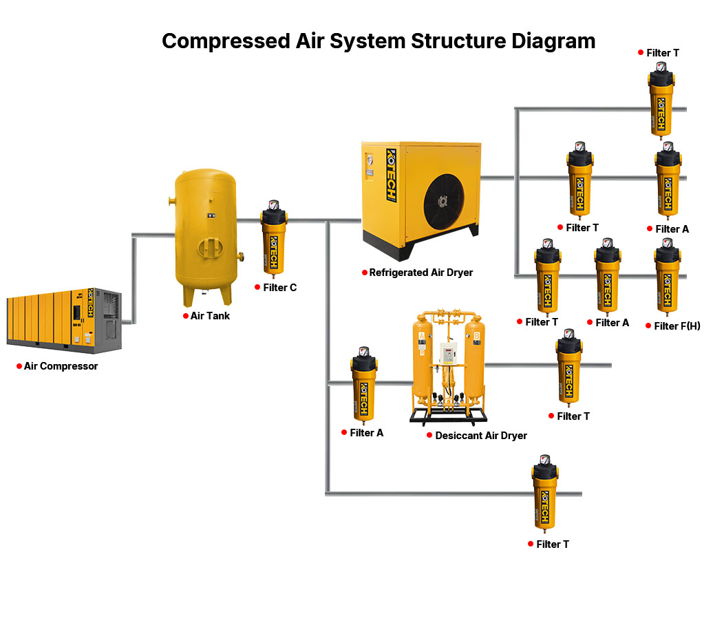
Screw Compressor Line Diagram
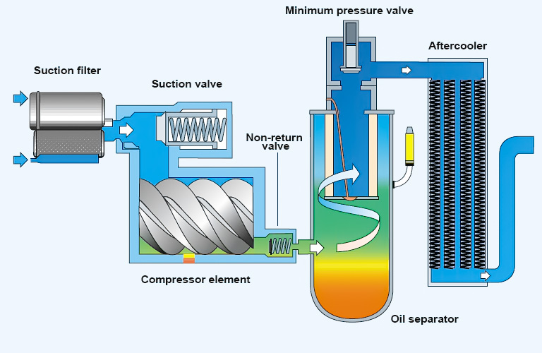
Composition of the air compressor system
In the air compressor control system, the pressure sensor installed on the air outlet pipe at the back end of the air compressoris usedto control the pressure of the air compressor.
When the air compressor starts, the loading solenoid valve is closed, the loading cylinder does not move, the frequency converter drags the motor to run unloaded for some time (can be set arbitrarily by the controller, set here for 10S), the loading solenoid valve opens, and the air compressor is running with load.
When the air compressor starts to run, if the back-end equipment uses a large amount of air, the pressure of compressed gas in the storage tank and the back-end pipeline does not reach the upper limit value of the pressure, then thecontroller will act on the loading valve, open the air inlet, and the motor will run under load, and continuously generate compressed gas to the back-end pipeline.
If the back-end gas equipment stops using gas, the pressure of compressed gas in the back-end pipeline and storage tank rises gradually, and whenit reaches the upper-pressure limit setting value, the pressure sensor sends out an unloading signal, the loading solenoid valve stops working, the air inlet filter closes, and the motor runs unloaded.
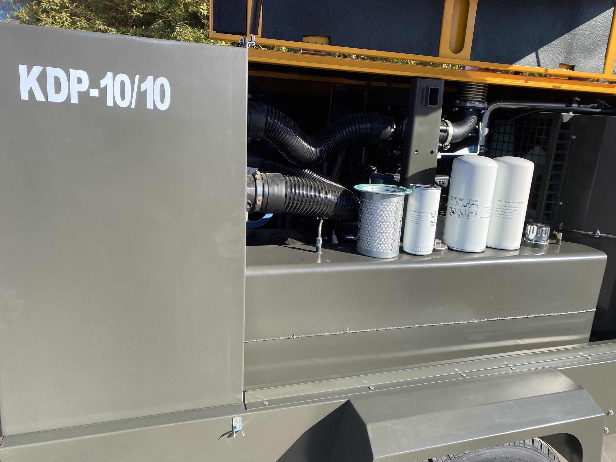
Diagram of Air Compressor Parts
10 major parts of air compressor
1. Oil circuit equipment
- Oil separator
The oil is separated from the refrigerant by the following conditions: 1) different flow rates of oil and gas; 2) flow to the oil tank after hitting the wall; 3) blockage after passing through the “atomiser assembly”.
- Oil filter
Cleanliness is indicated by the pressure drop, normal pressure drop < 1 bar, if DP (Differential Pressure) > 3.5 the filter is dirty and must be replaced.
- Oil heater
Oil heater: The heater is used during shutdown to prevent excess refrigerant from diluting into the oil, during compressor shutdown it should first be energised to run the heater before switching on the compressor.
- Oil level
Oil level: can be observed through the sight glass, usually the oil level should be maintained in the sight glass between 1/2 – 3/4, in any case, through the sight glass can be observed through the oil level, a long time or too much foam are indicated that the oil is diluted by the refrigerant.
2. Suction filter
Suction filter: used to eliminate impurities in the medium to protect the normal use of valves and equipment.
When the fluid enters the cartridge with a certain specification filter, the impurities are blocked, and the clean filtrate is discharged from the filter outlet.
3. Check valve
Stop valve: stop to prevent high-pressure gas from the condenser back to the compressor to prevent reverse pressure on the compressor and the resulting rotor reversal.
4. System protection devices
(1) Exhaust gas temperature monitoring: lack of oil can cause a sudden rise in exhaust gas temperature, the electronic protection module can monitor the exhaust gas temperature.
(2) Differential pressure switch HP / LP: the use of its on-off ability to control the on-off, in order to ensure that the equipment in the case of abnormal pressure can be closed in time to protect the equipment.
(3) Oil level control: It is recommended that in these applications (long piping arrangement, condenser remote arrangement) using oil level monitor to strictly control the oil level.
5. Cooling capacity control
According to the refrigeration capacity 100-75-50-25% adjustment, the slider has 4 corresponding positions, the slider is directly connected with the hydraulic cylinder moving slide valve, the position of the slide valve by the solenoid valve to control the actual shape of the slide valve to change the suction port.
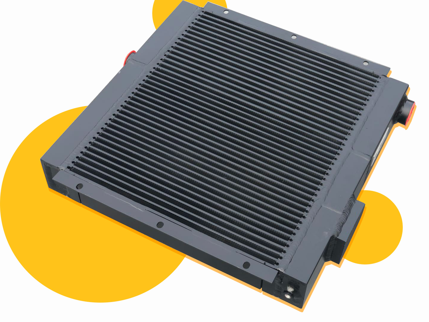
Air compressor coolers
6. Control panel: including voltmeter, pressure gauge, switch, and othercomponents,used to operate and monitor the operating status of the compressor.
7. valve system: including inlet valve, exhaust valve, and other components, used to control the air in and out and compression process.
8. noise reduction device: used to reduce the noise generated by the compressor work.
9. Air storage tank: used to store the compressed air and release it smoothly to the using equipment.
10. lubrication system: including lubricating oil tank, lubricating oil pump, lubricating oil filter, and other components, used to provide lubrication and cooling to the moving parts of the compressor.
10 major parts of air compressor parts components work together to enable air compressors to compress atmospheric air and provide it for use in a variety of industrial applications and DIY at home.
(Working principle of Air Compressor)
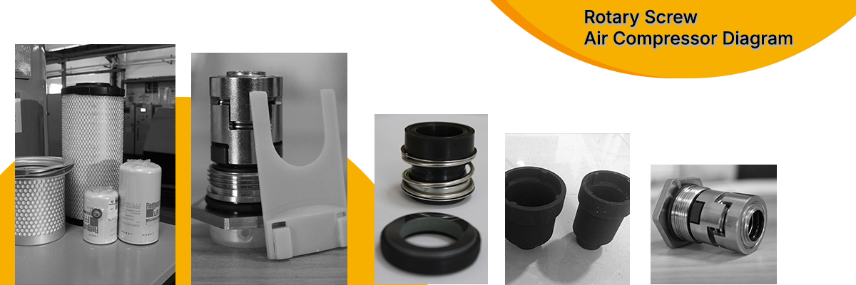
Rotary Screw Air Compressor Parts Diagram
- Spare Parts
Industry figures estimate that compressed air systems can waste up to 30% of the compressed air through leaks, poor control or lack of maintenance. Up time and performance is vital for your operation and selecting the right replacement air compressor parts is key.
Protect your equipment with Kotech’s wide range of spare parts and accessories. Genuine spare parts not only improve your air compressor’s life but also enhance its performance.
- Compressed Air System Controls
1、Dangerous places in Zone 1 and Zone 2 or dangerous places in Zone 20 and Zone 21.
2、IIA, IIB, IIC explosive gas environment or combustible dust environment;
3、Outdoor indoor (IP54/IP65).
4、Temperature group: T1-T4/T5/T6.
5、Applied in petroleum, chemical industry, aerospace and other places.
- Pressure Control Valves
Pressure Control Valves are devices used in air compressors to control the pressure of the compressed air. The valves open and close to maintain a constant pressure, and they can be adjusted to set the desired pressure.
They are usually located between the air compressor and the air tank, where they regulate the air pressure in the tank and keep it at a safe level.
FAQs (Frequently Asked Questions)

How we reset the working pressure from 7bar to be 8bar ?
Check how much the max pressure of the safety valve, if the max is 10bar, you can set :
1. Discharge pressure to be 8bar.
2. Loading pressure to be 6.5bar.
Above two reset in the user parameter.
3. Unloading pressure to be 8bar.
4. Stop pressure at 9bar.
Above two reset in the factory parameter.
Do you know the power required to run a 7.5kw 3m³ rotary screw air compressor?
Rated amp: 13.5A
Full load amp: 17A
Sarting amp: 52A
Can we get the spare parts inside the air end ?
Yes, you can advise which spare part you need and the qty .
How Does a Slide Valve Work on a Screw Compressor?
View Post: How Does a Slide Valve Work on a Screw Compressor?